Journal of Research in Dental
and Maxillofacial Sciences
Volume 11, Issue 2 (6-2026)
J Res Dent Maxillofac Sci 2026, 11(2): 114-125 |
Back to browse issues page

Ethics code: IR.TUMS.REC.1394.701
Download citation:
BibTeX | RIS | EndNote | Medlars | ProCite | Reference Manager | RefWorks
Send citation to:


BibTeX | RIS | EndNote | Medlars | ProCite | Reference Manager | RefWorks
Send citation to:
Niavarzi S, Geramipanah F, Sedighpour L, Marvi M. Effect of Gap Size between the Intracanal Post and Gutta-Percha on Stress Distribution in Teeth with Post-and-Core Restorations: A Finite Element Analysis. J Res Dent Maxillofac Sci 2026; 11 (2) :114-125
URL: http://jrdms.dentaliau.ac.ir/article-1-1506-en.html
URL: http://jrdms.dentaliau.ac.ir/article-1-1506-en.html


1- Private Endodontist, Tehran, Iran
2- Department of Prosthodontics, School of Dentistry, Tehran University of Medical Sciences, Tehran, Iran
3- Department of Endodontics, School of Dentistry, Tehran University of Medical Sciences, Tehran, Iran. ,Mohammadmarvi.68@gmail.com
2- Department of Prosthodontics, School of Dentistry, Tehran University of Medical Sciences, Tehran, Iran
3- Department of Endodontics, School of Dentistry, Tehran University of Medical Sciences, Tehran, Iran. ,
Full-Text [PDF 555 kb]
(4 Downloads)
| Abstract (HTML) (7 Views)
Full-Text: (1 Views)
Abstract
Background and Aim: This study evaluated the effect of gap size between the intracanal post and gutta-percha on stress distribution in teeth with post-and-core restorations using finite element analysis (FEA).
Materials and Methods: In this FEA, eight 3D models of maxillary central incisors were created: four with fiber-reinforced composite posts (FRCPs) and four with nickel-chromium metal cast posts (MCPs). Also, 0 mm (no gap), 1 mm, 2 mm, and 3 mm gaps were modeled. A 100-N oblique load (at 135 degrees relative to the longitudinal tooth axis) was applied, and the von Mises (VM), tensile, and compressive stress values were analyzed.
Results: For the FRCPs, the VM stress patterns in dentin remained consistent in presence of 0-2 mm gap, but a 3-mm gap increased stress by 35%-37%. The MCP models showed similar stress distribution patterns across different gap sizes, with a peak VM stress (13.11 MPa) localized at the buccal mid-root. The FRCPs demonstrated uniform stress distribution; whereas, the MCPs exhibited higher overall stress levels by 85%-89%.
Conclusion: The results indicated that a 3-mm gap significantly elevated dentinal stress, increasing the fracture risk. The FRCPs with ≤ 2 mm gap had an optimal performance; whereas, the MCPs induced higher stress levels regardless of the gap size. Failure modes differed as well, such that the FRCPs were predisposed to cervical fractures, whereas the MCPs increased the risk of apical fractures. These findings highlight the importance of management of intracanal post-gutta-percha gap as a critical parameter in post-and-core restorations to mitigate biomechanical failure.
Keywords: Dental Stress Analysis; Post and Core Technique; Root Canal Therapy
Introduction
Excessive loss of tooth structure due to caries and coronal fracture often necessitates root canal treatment. The root canal treatment process increases cuspal deflection during function, which may lead to tooth fracture, particularly in the presence of mesio-occluso-distal cavities [1].
Evidence shows that tooth rigidity decreases by 46% following the loss of one marginal ridge, and by 63% following the loss of both marginal ridges [2]. Endodontically treated teeth, being nonvital, are restored using various methods, such as direct restorations or the post‑and‑core technique. Preserving the tooth structure and ensuring adequate bonding of restorative materials are essential for achieving predictable and successful treatment outcomes [1]. Intracanal posts are required to retain the core material and distribute stresses in teeth that have lost over 50% of their coronal structure [3]. Moreover, post‑and‑core restorations have been associated with higher success rates [1].
Post space preparation should be performed such that 3–5 mm of gutta-percha remains in the apical third of the root canal [4]. Microleakage is influenced by the root canal treatment method, quality of obturation, timing of post space preparation, and the post cementation technique. After post cementation in endodontically treated teeth, a gap typically exists between the apical end of the intracanal post and the most coronal portion of gutta-percha. This gap between the intracanal post and the remaining root filling material is another factor that can contribute to microbial ingress following post-and-core restorations [4, 5]. Ideally, no gap should remain between the intracanal post and gutta-percha [6].
Post material is a primary criterion for classification of intracanal posts; accordingly, intracanal posts may be categorized into metal, non-metal, and fiber-reinforced composite posts (FRCPs). Metal posts are categorized into custom-made metal cast posts (MCPs) and prefabricated posts [7]. Cast post-and-core restorations have been employed for decades, exhibiting high survival rates (74–94% over 17 years), with a longevity comparable to that of restorations in vital teeth. Thus, cast post-and-core restorations are the gold standard for restoring endodontically treated teeth [8].
The main advantages of FRCPs, with an elastic modulus of 12 GPa, are their enhanced esthetics and a modulus of elasticity similar to that of dentin (approximately 18 GPa). Consequently, occlusal forces and stresses are distributed more uniformly along the root dentin, reducing the risk of vertical root fracture, which is a common clinical occurrence [7, 9]. Other benefits of these posts include their ability to transmit light from curing units along the post within the root canal, and their capacity to bond effectively to resin cements. Moreover, these posts exhibit high tensile strength and fatigue resistance [10].
In a one-year follow-up of patients treated with post‑and‑core restorations, root‑related complications occurred more frequently when there was a gap between the post‑and‑core and the gutta‑percha. However, about one‑third of these patients were asymptomatic [11].
Coronal microleakage is one of the proposed causes of failure in endodontically treated teeth restored with post‑and‑core systems, when a gap exists between the post and gutta‑percha [11, 12]. Despite the availability of numerous in vitro studies, it remains unclear which post system is optimal, especially with respect to the generated stresses. Some researchers recommend posts with a high modulus of elasticity [13], whereas some favor posts with a modulus of elasticity closer to that of dentin [13, 14]. In contrast, some others found no significant difference between them [14].
The null hypothesis of our study was that neither the size of the gap between the intracanal post and the remaining gutta‑percha (0, 1, 2, or 3 mm) nor the type of post material (FRCP vs. nickel‑chromium MCP) would significantly affect the magnitude or distribution of von Mises (VM), tensile, or compressive stresses in any component of the restored tooth. Therefore, this finite element analysis aimed to evaluate the pattern of stress distribution in endodontically treated maxillary central incisors restored with post‑and‑core restorations under these conditions.
Materials and Methods
To generate a digital model in this FEA study, an extracted human maxillary central incisor with no caries or fracture was initially examined under a stereomicroscope (Dino-Lite, Taiwan) at x10 magnification (ethical approval code: IR.TUMS.REC.1394.701). Subsequently, the mesiodistal and buccolingual dimensions and the root length of the tooth were measured with a digital caliper (Mitutoyo Corp., Kawasaki, Kanagawa, Japan). The tooth then underwent standard root canal treatment, with a #20 initial file (Mani Corp. Japan) and a #35 master file (Mani Corp. Japan). Step-back flaring was performed up to a #50 file, and a #35 master cone (DiaDent, South Korea) was chosen. The canal was then obturated using the lateral compaction technique with #20 accessory gutta-percha points and AH26 sealer (Dentsply Sirona, Charlotte, NC, USA). After determining the root length, the coronal two-thirds of the root filling was removed using #2 and #3 peeso reamers (Mani Inc., Tochigi, Japan), and the canal was irrigated with saline. Next, the tooth crown was sectioned under water spray using a diamond bur mounted on a high-speed handpiece (868B.314.018; Komet Dental, Lemgo, Germany) such that a 1-mm ferrule remained above the cementoenamel junction. The 1-mm ferrule was intended to simulate the worst acceptable clinical scenario [14]. Finally, the resin pattern for the post-and-core was fabricated directly using auto-polymerizing acrylic resin (GC Pattern Resin; GC America Inc., Alsip, IL, USA). The final preparation design consisted of a full-ceramic crown preparation with a sound shoulder finish line and a 12-degree taper.
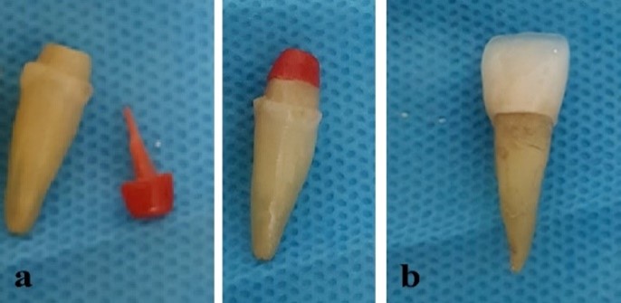
The tooth was first mounted in a gypsum mold (Moldano, Kimia Dent, Tehran, Iran) to fabricate a ceramic crown for a central incisor, and a layer of resin wax (Acropars, Marlic Medical Industries Co., Tehran, Iran) was applied on its surface. A custom tray was fabricated using VLC (Mega Light Tray, Liechtenstein, Germany). After curing the VLC in a light-curing unit (Woodpecker, Guilin, China), the resin wax was removed from the tooth, and an impression was made using addition silicone impression material (Wash Panasil, Eschenburg, Germany). The impression was then sent to a laboratory for fabrication of an all-ceramic zirconia crown (Vita Zahnfabrik, Bad Sackingen, Germany) (Figure 1). Subsequently, adaptation of the crown on the tooth was evaluated using Fit Checker (Dent X Fit Checker, Tehran, Iran) to ensure complete seating.
Figure 1. (a) Tooth preparation and placement of a post-and-core restoration. (b) Fabricated full-ceramic crown
Next, each component of the tooth, the post‑and‑core, and the crown, was individually scanned using a 3D optical laboratory scanner (Rangevision, Muenchen, Germany) with a 50-μm accuracy, and modeling was performed using Catia 21.0 software (Dassault Systèmes, Vélizy-Villacoublay, France).
In the resulting models, the post, tooth, and crown were merged, and the cortical bone was modeled with 1 mm thickness in the buccal and lingual sides. The cancellous (spongy) bone was modeled with 2 mm thickness in the mesial and distal surfaces, and 1 mm thickness in the buccal and lingual surfaces. Moreover, the periodontal ligament was modeled with 25 μm thickness, and a cement layer of 50 μm was considered in all regions, including between the post‑and‑core and dentin, at the apical end of the post, and between the crown and the core [15,16].
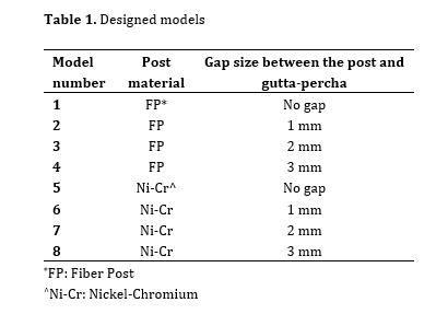
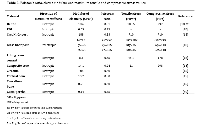
Table 1 presents the models evaluated in this study. The models were exported as STP files (a format compatible with Ansys) and imported into Ansys version 16 (ANSYS Inc., Canonsburg, PA, USA) (Figure 2). The mechanical properties of all materials used, including their Poisson’s ratio and elastic modulus, were entered into the software (Table 2). The finite element model was then generated and analyzed using Ansys version 16.
Table 1. Designed models
Figure 2. Modeling of the tooth and bone: (a) Buccal view. (b) Palatal view
In all fiber post models, the composite core was assumed to be bonded to dentin. All components, except for the fiber post, were considered isotropic, linearly elastic, and homogeneous [17]. The fiber post was modeled as orthotropic [15]. The support points were applied to the cortical bone. Meshing was performed using tetrahedral elements via the Ansys meshing module, resulting in a final model with 28,655 elements and 54,591 nodes. The maximum element size was set to 0.5 mm in critical regions (post‑dentin interface, ferrule area, and post‑gutta‑percha gap region), and mesh quality was verified by ensuring that element skewness remained below 0.85 and aspect ratio below 5 for > 98% of elements, in accordance with typical convergence criteria for dental FEA models [15,18]. A 100-N load was applied at an angle of 135 degrees relative to the tooth's longitudinal axis in all models. Subsequent post-processing yielded the stress results in terms of the VM stress contours, principal stresses (both tensile and compressive), and shear stresses. A convergence test was conducted to ensure the accuracy of the constructed model [19].
Results
The tooth was first mounted in a gypsum mold (Moldano, Kimia Dent, Tehran, Iran) to fabricate a ceramic crown for a central incisor, and a layer of resin wax (Acropars, Marlic Medical Industries Co., Tehran, Iran) was applied on its surface. A custom tray was fabricated using VLC (Mega Light Tray, Liechtenstein, Germany). After curing the VLC in a light-curing unit (Woodpecker, Guilin, China), the resin wax was removed from the tooth, and an impression was made using addition silicone impression material (Wash Panasil, Eschenburg, Germany). The impression was then sent to a laboratory for fabrication of an all-ceramic zirconia crown (Vita Zahnfabrik, Bad Sackingen, Germany) (Figure 1). Subsequently, adaptation of the crown on the tooth was evaluated using Fit Checker (Dent X Fit Checker, Tehran, Iran) to ensure complete seating.
Figure 1. (a) Tooth preparation and placement of a post-and-core restoration. (b) Fabricated full-ceramic crown
Next, each component of the tooth, the post‑and‑core, and the crown, was individually scanned using a 3D optical laboratory scanner (Rangevision, Muenchen, Germany) with a 50-μm accuracy, and modeling was performed using Catia 21.0 software (Dassault Systèmes, Vélizy-Villacoublay, France).
In the resulting models, the post, tooth, and crown were merged, and the cortical bone was modeled with 1 mm thickness in the buccal and lingual sides. The cancellous (spongy) bone was modeled with 2 mm thickness in the mesial and distal surfaces, and 1 mm thickness in the buccal and lingual surfaces. Moreover, the periodontal ligament was modeled with 25 μm thickness, and a cement layer of 50 μm was considered in all regions, including between the post‑and‑core and dentin, at the apical end of the post, and between the crown and the core [15,16].
Table 1 presents the models evaluated in this study. The models were exported as STP files (a format compatible with Ansys) and imported into Ansys version 16 (ANSYS Inc., Canonsburg, PA, USA) (Figure 2). The mechanical properties of all materials used, including their Poisson’s ratio and elastic modulus, were entered into the software (Table 2). The finite element model was then generated and analyzed using Ansys version 16.
Table 1. Designed models
Figure 2. Modeling of the tooth and bone: (a) Buccal view. (b) Palatal view
In all fiber post models, the composite core was assumed to be bonded to dentin. All components, except for the fiber post, were considered isotropic, linearly elastic, and homogeneous [17]. The fiber post was modeled as orthotropic [15]. The support points were applied to the cortical bone. Meshing was performed using tetrahedral elements via the Ansys meshing module, resulting in a final model with 28,655 elements and 54,591 nodes. The maximum element size was set to 0.5 mm in critical regions (post‑dentin interface, ferrule area, and post‑gutta‑percha gap region), and mesh quality was verified by ensuring that element skewness remained below 0.85 and aspect ratio below 5 for > 98% of elements, in accordance with typical convergence criteria for dental FEA models [15,18]. A 100-N load was applied at an angle of 135 degrees relative to the tooth's longitudinal axis in all models. Subsequent post-processing yielded the stress results in terms of the VM stress contours, principal stresses (both tensile and compressive), and shear stresses. A convergence test was conducted to ensure the accuracy of the constructed model [19].
Results
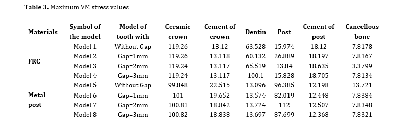
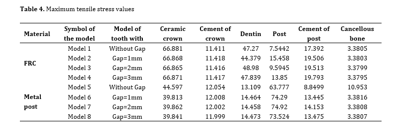
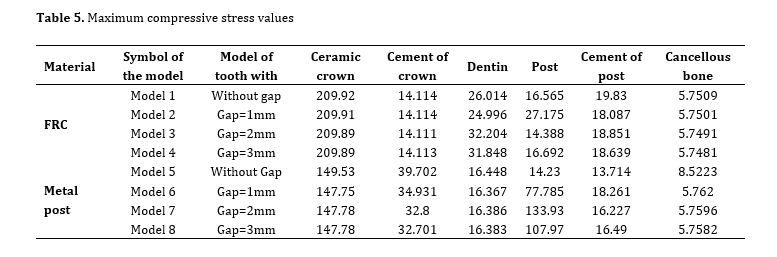
The maximum VM stress values of the eight models in this study are summarized in Table 3. The maximum tensile and compressive stress values are presented in Tables 4 and 5, respectively. All stress values were deterministic outputs from single FEA models; therefore, standard deviation was not applicable. The VM and principal stresses for each of the analyzed components were as follows:
Dentin
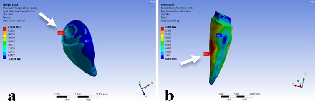
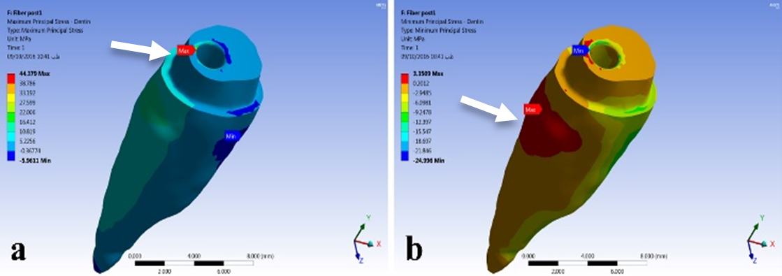
The magnitude and distribution of VM stress values in dentin were similar for all fiber post models with either no gap or with 1- and 2‑mm gaps, except for Model 4 (fiber post with a 3‑mm gap), which exhibited an increase of 35%–37%. For example, the peak von Mises stress in dentin (Table 3) was 63.5 MPa for the FRCP‑0 mm model and 100.1 MPa for the FRCP‑3 mm model. In the aforementioned models, the highest stress value was observed at the canal orifice. Additionally, the VM stress pattern in dentin was similar in all MCP models, with the highest stress (approximately 13.11 MPa) observed in the buccal side at the mid-root region (Figure 3).
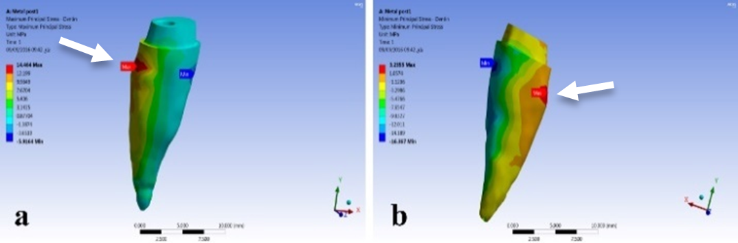
In the fiber post group, the tensile and compressive stress values in dentin were predominantly concentrated at the canal orifice. However, in MCP, stress was concentrated at the junction of the coronal third and middle third at the dentin–bone interface, with the tensile stress concentrated on the palatal side and compressive stress on the buccal side. In dentin, the tensile stress values were 44–48 MPa in the fiber post group, compared to 13–14 MPa in the MCP group, approximately 71% higher in the fiber post group. Similarly, the compressive stress in the fiber post group ranged from 24 MPa to 32 MPa; whereas it was around 16 MPa in the MCP group, meaning that the compressive stress was 34%–50% higher in the fiber post models.
In the fiber post group, the tensile and compressive stress values in dentin were predominantly concentrated at the canal orifice. However, in MCP, stress was concentrated at the junction of the coronal third and middle third at the dentin–bone interface, with the tensile stress concentrated on the palatal side and compressive stress on the buccal side. In dentin, the tensile stress values were 44–48 MPa in the fiber post group, compared to 13–14 MPa in the MCP group, approximately 71% higher in the fiber post group. Similarly, the compressive stress in the fiber post group ranged from 24 MPa to 32 MPa; whereas it was around 16 MPa in the MCP group, meaning that the compressive stress was 34%–50% higher in the fiber post models.
Table 2. Poisson's ratio, elastic modulus, and maximum tensile and compressive stress values
Table 3. Maximum VM stress values
Table 4. Maximum tensile stress values
Table 5. Maximum compressive stress values
The maximum tensile stress in dentin ranged from 44–48 MPa for fiber post models, versus 13–14 MPa in MCP models; thus, the tensile stress was approximately 71% higher in the fiber post models than the MCP models (Figures 4 and 5).
Post
The magnitude and distribution of VM stress values in fiber posts were consistent across Models 1 to 4, exhibiting a uniform pattern. In contrast, the VM stress in MCPs was not uniform and was approximately 85%–89% higher than that in fiber posts. Moreover, the compressive and tensile stresses in MCPs were 82% and 83%–89% higher, respectively, compared to fiber posts.
Fiber posts had a compressive stress of 150 MPa and a tensile stress of 210 MPa. In the fiber post group, the highest compressive stress recorded across the models was 27.175 MPa, and the maximum tensile stress was 15.458 MPa (in Model 2). These values were well below the maximum load-bearing capacity of fiber posts. On the other hand, MCPs exhibited compressive and tensile stresses of 710 MPa, with maximum compressive and tensile stress values of 133.93 MPa and 74.92 MPa, respectively (in Model 7).
Fiber posts had a compressive stress of 150 MPa and a tensile stress of 210 MPa. In the fiber post group, the highest compressive stress recorded across the models was 27.175 MPa, and the maximum tensile stress was 15.458 MPa (in Model 2). These values were well below the maximum load-bearing capacity of fiber posts. On the other hand, MCPs exhibited compressive and tensile stresses of 710 MPa, with maximum compressive and tensile stress values of 133.93 MPa and 74.92 MPa, respectively (in Model 7).
Composite Core
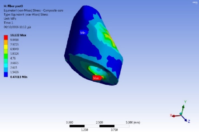
The composite core's VM, tensile, and compressive stress distributions showed negligible differences across all fiber post models, with the highest VM stress concentrated at the post-core interface (Figure 6).
Cancellous Bone
In the cancellous bone, all models showed the highest VM, tensile, and compressive stress values in the palatal cervical region.
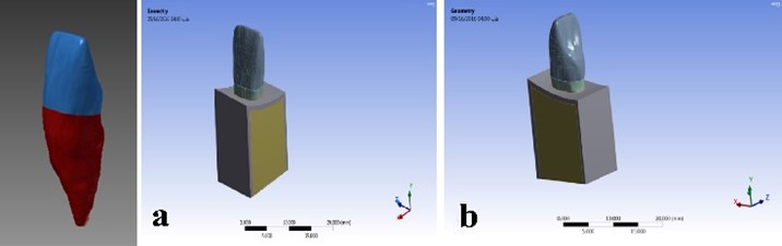
Figure 4. Distribution of compressive and tensile stresses (MPa) in dentin for a representative fiber post model (FRCP, 1 mm gap). Lingual external view of the root (maxillary central incisor). (a) Compressive stress: highest concentration (≈27 MPa) at canal orifice (white arrow). (b) Tensile stress: highest concentration (≈15 MPa) at post‑core interface (white arrow). Blue arrow = minimum stress, red arrow = maximum stress (values in MPa).
Figure 5. Mesial external view of the root (maxillary central incisor) showing stress distribution in dentin for a metal cast post model (MCP, Model 6, 1 mm gap). (a) Highest concentration of compressive stress (≈13.6 MPa) at the dentin‑bone interface on the buccal side (white arrow). (b) Highest concentration of tensile stress (≈14.5 MPa) at the dentin‑bone interface on the palatal side (white arrow). Blue arrow = minimum stress, red arrow = maximum stress (values in MPa).
Figure 6. Three‑dimensional isometric view of the composite core (fiber post model, representative gap) showing the distribution of VM stress (MPa). Maximum stress (≈10.1 MPa) is concentrated at the post‑core interface (white arrow), while minimum stress (≈0.5 MPa) occurs in the bulk of the core. Blue arrow = minimum stress, red arrow = maximum stress (values in MPa).
Discussion
This study used FEA to evaluate the effect of gap size between the post and the remaining gutta-percha on stress distribution in teeth with post‐and‐core restoration. The null hypothesis was rejected for the effect of gap size on FRCP (a 3‑mm gap significantly increased dentinal stress) and for the comparison between post materials (FRCPs and MCPs produced markedly different stress levels and patterns). The null hypothesis was accepted for the effect of gap size on MCPs, where dentinal stress remained nearly unchanged regardless of the gap. Similar to the present study, comparable FEA studies on post‐and‐core restorations used convergence tests to validate the models [15,20]. The present study used tetrahedral elements 2.0 mm in size. Also, due to the complex geometry of the tooth model, Ansys software employs these elements by default. As expected, other similar studies also utilized tetrahedral elements 2.0 mm in size [21-23]. In general, structural failure occurs due to compressive, tensile, and shear stresses applied to materials [15]. Various criteria, including the VM, principal, and shear stresses, can be employed to assess stress distribution in different parts of a tooth model. Although many failure, this approach is principally applicable to materials for which the maximum tensile and compressive stress values are equal (as is the case with metals) [18].
In post‐and‐core models using materials such as ceramics or dentin, the compressive stress is several times greater than the tensile stress; hence, the VM criterion is unsuited for these materials. Therefore, in the present study, VM stress values were used exclusively as a relative comparative index to rank the biomechanical performance of different models (e.g., comparing gap sizes or post materials), not as an absolute predictor of clinical failure. For materials like dentin, a more accurate failure assessment would require modified VM criteria or principal‑stress‑based criteria that account for the marked difference between tensile and compressive stresses. Future FEA studies should consider implementing such modified criteria to improve predictive accuracy. In our study, this parameter (VM criterion) was adopted. It should be noted that one previous study employed the modified VM criterion as an alternative [18]. Nevertheless, given the limited number of studies utilizing this concept and the challenges in comparing their results, the modified VM criterion was not used in the present study. Future investigations are recommended to employ criteria such as the modified VM.
In the present study, stress concentration in dentin occurred at the canal orifice in the fiber post models. In contrast, in the MCP models, stress was concentrated in the cervical region on the palatal side of the tooth. The maximum dentin stress was considerably lower in the MCP models compared to the fiber post models. In other words, fiber posts transfer most of the stress to the surrounding dentin, whereas MCPs transfer less stress to the adjacent dentin. However, the stress concentration pattern in fiber posts leads to a more favorable type of failure, whereas MCPs carry a higher risk of dentin and root fracture [23].
This finding is corroborated by clinical studies, reporting that fiber posts usually fail in a location amenable to repair. In contrast, failure of cast posts usually manifests as a catastrophic fracture. Nonetheless, since MCPs impart a lower force onto the tooth, they ultimately enhance the fracture resistance of the tooth. In vitro studies have also demonstrated that fracture of teeth with MCPs requires a more significant load than with fiber posts [13, 24, 25]. Consequently, it can be stated that MCPs increase the tooth’s resistance to fracture, a conclusion further supported by numerous FEA studies [18,25].
Badami et al. [14] in their systematic review reported that stress distribution in fiber posts was predominantly cervical. In contrast, González-Lluch et al. [22], unlike the current study, reported that stress in fiber posts was concentrated in dentin at the cementoenamel junction. It is important to note that in their study, load was applied at an angle of 30 degrees, and the fiber posts were modeled as isotropic with a ferrule value of zero. This combination of factors may account for their contradictory results.
Stress concentration in dentin in the presence of MCPs, as in the present study, has been reported at the post–dentin interface in the cervical region of the palatal side [22]. Dejak and Młotkowski [18] also reported that stress in MCPs was concentrated in the tooth’s cervical (ferrule) region. Similarly, Santos-Filho et al. [19] found that in MCPs, stress concentration in dentin occurred at the ferrule–post interface, which is consistent with the present findings. Furthermore, Dejak and Młotkowski [18] reported that teeth restored with cast (metal) post-and-core restorations exhibited lower stress levels compared to those restored with FRCPs. Durmuş and Oyar [13] and Al-Omiri et al. [23] observed that posts with a lower elastic modulus transfer more stress to the root while generating lower internal stresses within the post. In contrast, posts with a higher elastic modulus retain most of the stress, thereby transmitting less stress to the root.
In the MCP models, dentin stress remained nearly constant with the increasing gap between the post and gutta-percha; whereas dentin stress varied with gap size in the fiber post group. As noted earlier, the internal stresses within metal posts were substantially higher than those within fiber posts. The tensile stress at the margin of MCPs was 27% to 53% lower than that at the margin of fiber posts, and the compressive stress around MCPs was up to 30% lower compared with fiber posts. Abdulmunem et al. [26] noted that when components with different stiffness values interface, stress is concentrated within the stiffer element. Consequently, the highest stress tends to occur in the adjacent, less rigid component, leading to crack formation and eventual fracture. Therefore, it is anticipated that in MCP restorations, the adjacent margin with its lower stiffness may be more susceptible to failure.
In all models, whether employing fiber or metal posts, stress concentration in the cancellous bone was observed in the cervical region of the palatal side, with similar stress levels detected across models. Hsu et al. [16] and Ferrari et al. [27] also reported that the highest bone stress occurred in the cervical region.
Our findings on post material effects are consistent with several FEA studies on maxillary central incisors. The influence of ferrule height on stress distribution was also confirmed by Juloski et al. [15] and Santos‑Filho et al. [19], who noted that increasing ferrule height reduces stress at post‑core interfaces (a factor we controlled by standardizing ferrule height to 1 mm to isolate the gap effect). Badami et al. [14] systematically reviewed different post materials and confirmed that fiber posts produce more favorable cervical stress distribution, which is consistent with our observation that FRCP failures are more cervical and restorable.
While prior FEA studies have extensively evaluated post material, ferrule height, and post length [13-15,19,23], none — to our knowledge — have systematically modeled the geometric gap between the post apex and the residual gutta‑percha as a discrete variable. Clinical reports have associated gaps exceeding 2 mm with poorer outcomes, but the biomechanical mechanism remained largely unexplored. Our study extends this clinical knowledge by quantifying the stress consequences of such gaps: a 3-mm gap increases dentinal VM stress by 35%–37% in FRCPs and elevates shear stress at the post‑core interface to near‑failure levels. Thus, our “gap‑size” parameter adds a new dimension to existing FEA‑based knowledge, highlighting that post‑space preparation accuracy is a critical, modifiable variable that interacts with post material to determine failure risk.
In the current study, the introduction of a gap between the fiber post and the gutta-percha resulted in higher VM stress values at the interface between the core and the fiber post. The stresses generated in dentin in the presence of a 3-mm gap were significantly higher than those observed with 1‐ and 2‐mm gaps, potentially leading to treatment failure. Moshonov et al. [12] found that clinical outcomes were significantly compromised when the gap between the gutta-percha and the cemented post exceeded 2 mm, and only a 29% success rate was observed for post-endodontic restorations; whereas, after 5 years, 83% of the teeth restored without any gap between the post and gutta-percha demonstrated a favorable outcome. Similarly, Ozkurt et al. [11] reported that none of the 207 teeth exhibited a gap between the post and the root canal filling in cases with a satisfactory root canal treatment. In the gap-free group, 135 teeth (65%) showed healthy periapical tissues; whereas 72 (35%) presented signs of apical periodontitis. In contrast, a gap was observed between the remaining root canal filling and the post in 81 teeth; among which, 69 cases (85%) exhibited periapical pathosis; whereas only 12 teeth (15%) maintained healthy periapical tissues. Furthermore, in a study by Sayed et al. [5], unfavorable clinical outcomes were observed in 50% of maxillary posterior teeth when the gap between the post and gutta-percha exceeded 1 mm.
In the present study, when a force of 100 N at an angle of 135 degrees was applied to the tooth, all model components exhibited a very low fracture probability, with the stress values substantially below the tooth’s failure limits. However, one exception was observed at the post and composite core interface, where the measured shear stresses were highly close to the shear strength threshold of the interface. This finding suggests that, should failure occur, it would most likely initiate from this region. Other studies, especially clinical investigations, have reported debonding of the post [27, 28].
Furthermore, the results of the present study indicated that the shear stress within the fiber posts with an interfacial gap exceeded the fiber post’s shear strength, leading to potential failure in that area. In other words, fiber posts appear to be considerably more sensitive to an increase in gap size (and the corresponding shorter post length) than cast posts. Thus, extra caution should be exercised when working with fiber posts. These findings contradict those of Hsu et al, [16] possibly because their study did not evaluate shear stress at the post-core interface.
A nuanced interpretation of our findings is necessary when comparing them with clinical and in vitro studies that report higher fracture resistance for cast post‑and‑core restorations [13,23,24]. At first glance, the apparent paradox is that MCPs in our FEA showed lower dentinal stress (13–14 MPa tensile) but very high internal post stress; whereas FRCPs exhibited higher dentinal stress (44–48 MPa) but lower internal stress. How can a post that imposes less stress on dentin be associated with higher fracture resistance? The answer lies in the distinction between fracture load and failure mode. Cast posts, due to their high elastic modulus, absorb and store most of the occlusal energy within the post itself [13,23]. This protects the dentin from high stress, thus a greater force is required to fracture the tooth – hence the higher fracture resistance values reported in load‑to‑failure tests [24]. However, when failure eventually occurs, the stored energy is released catastrophically, often resulting in non‑restorable vertical or apical root fractures [11,24]. In contrast, fiber posts with a lower elastic modulus transfer stress more uniformly to the surrounding dentin [14]. This leads to higher recorded dentinal stress values, but the failure pattern is typically cervical, limited to the core‑post interface, and often restorable [27,28]. In this sense, fiber posts act as a “biomechanical fuse”: they fail earlier but in a more predictable and repairable manner. Therefore, the term “fracture resistance” should not be interpreted in isolation. Clinicians must weigh trade‑offs: a cast post may offer higher load tolerance, but at the cost of a potentially unrestorable apical fracture. A fiber post, while showing higher dentinal stress in FEA, provides a more favorable failure mode and preserves the possibility of re‑treatment. Our study indicates that the advantage of fiber posts remains intact only when the gutta-percha gap at the post is ≤ 2 mm; a gap of 3 mm negates this benefit by elevating shear stress at the post-core interface. This nuance is essential for translating FEA findings into clinical practice. This nuance is essential for translating FEA findings into clinical practice.
It should also be noted that FEA studies possess inherent limitations. For example, the mechanical properties assigned to the modeled structures may not perfectly reflect absolute values, and the model dimensions are only approximate, potentially influenced by inter-individual differences.
Conclusion
In post‐and‐core models using materials such as ceramics or dentin, the compressive stress is several times greater than the tensile stress; hence, the VM criterion is unsuited for these materials. Therefore, in the present study, VM stress values were used exclusively as a relative comparative index to rank the biomechanical performance of different models (e.g., comparing gap sizes or post materials), not as an absolute predictor of clinical failure. For materials like dentin, a more accurate failure assessment would require modified VM criteria or principal‑stress‑based criteria that account for the marked difference between tensile and compressive stresses. Future FEA studies should consider implementing such modified criteria to improve predictive accuracy. In our study, this parameter (VM criterion) was adopted. It should be noted that one previous study employed the modified VM criterion as an alternative [18]. Nevertheless, given the limited number of studies utilizing this concept and the challenges in comparing their results, the modified VM criterion was not used in the present study. Future investigations are recommended to employ criteria such as the modified VM.
In the present study, stress concentration in dentin occurred at the canal orifice in the fiber post models. In contrast, in the MCP models, stress was concentrated in the cervical region on the palatal side of the tooth. The maximum dentin stress was considerably lower in the MCP models compared to the fiber post models. In other words, fiber posts transfer most of the stress to the surrounding dentin, whereas MCPs transfer less stress to the adjacent dentin. However, the stress concentration pattern in fiber posts leads to a more favorable type of failure, whereas MCPs carry a higher risk of dentin and root fracture [23].
This finding is corroborated by clinical studies, reporting that fiber posts usually fail in a location amenable to repair. In contrast, failure of cast posts usually manifests as a catastrophic fracture. Nonetheless, since MCPs impart a lower force onto the tooth, they ultimately enhance the fracture resistance of the tooth. In vitro studies have also demonstrated that fracture of teeth with MCPs requires a more significant load than with fiber posts [13, 24, 25]. Consequently, it can be stated that MCPs increase the tooth’s resistance to fracture, a conclusion further supported by numerous FEA studies [18,25].
Badami et al. [14] in their systematic review reported that stress distribution in fiber posts was predominantly cervical. In contrast, González-Lluch et al. [22], unlike the current study, reported that stress in fiber posts was concentrated in dentin at the cementoenamel junction. It is important to note that in their study, load was applied at an angle of 30 degrees, and the fiber posts were modeled as isotropic with a ferrule value of zero. This combination of factors may account for their contradictory results.
Stress concentration in dentin in the presence of MCPs, as in the present study, has been reported at the post–dentin interface in the cervical region of the palatal side [22]. Dejak and Młotkowski [18] also reported that stress in MCPs was concentrated in the tooth’s cervical (ferrule) region. Similarly, Santos-Filho et al. [19] found that in MCPs, stress concentration in dentin occurred at the ferrule–post interface, which is consistent with the present findings. Furthermore, Dejak and Młotkowski [18] reported that teeth restored with cast (metal) post-and-core restorations exhibited lower stress levels compared to those restored with FRCPs. Durmuş and Oyar [13] and Al-Omiri et al. [23] observed that posts with a lower elastic modulus transfer more stress to the root while generating lower internal stresses within the post. In contrast, posts with a higher elastic modulus retain most of the stress, thereby transmitting less stress to the root.
In the MCP models, dentin stress remained nearly constant with the increasing gap between the post and gutta-percha; whereas dentin stress varied with gap size in the fiber post group. As noted earlier, the internal stresses within metal posts were substantially higher than those within fiber posts. The tensile stress at the margin of MCPs was 27% to 53% lower than that at the margin of fiber posts, and the compressive stress around MCPs was up to 30% lower compared with fiber posts. Abdulmunem et al. [26] noted that when components with different stiffness values interface, stress is concentrated within the stiffer element. Consequently, the highest stress tends to occur in the adjacent, less rigid component, leading to crack formation and eventual fracture. Therefore, it is anticipated that in MCP restorations, the adjacent margin with its lower stiffness may be more susceptible to failure
In all models, whether employing fiber or metal posts, stress concentration in the cancellous bone was observed in the cervical region of the palatal side, with similar stress levels detected across models. Hsu et al. [16] and Ferrari et al. [27] also reported that the highest bone stress occurred in the cervical region.
Our findings on post material effects are consistent with several FEA studies on maxillary central incisors. The influence of ferrule height on stress distribution was also confirmed by Juloski et al. [15] and Santos‑Filho et al. [19], who noted that increasing ferrule height reduces stress at post‑core interfaces (a factor we controlled by standardizing ferrule height to 1 mm to isolate the gap effect). Badami et al. [14] systematically reviewed different post materials and confirmed that fiber posts produce more favorable cervical stress distribution, which is consistent with our observation that FRCP failures are more cervical and restorable.
While prior FEA studies have extensively evaluated post material, ferrule height, and post length [13-15,19,23], none — to our knowledge — have systematically modeled the geometric gap between the post apex and the residual gutta‑percha as a discrete variable. Clinical reports have associated gaps exceeding 2 mm with poorer outcomes, but the biomechanical mechanism remained largely unexplored. Our study extends this clinical knowledge by quantifying the stress consequences of such gaps: a 3-mm gap increases dentinal VM stress by 35%–37% in FRCPs and elevates shear stress at the post‑core interface to near‑failure levels. Thus, our “gap‑size” parameter adds a new dimension to existing FEA‑based knowledge, highlighting that post‑space preparation accuracy is a critical, modifiable variable that interacts with post material to determine failure risk.
In the current study, the introduction of a gap between the fiber post and the gutta-percha resulted in higher VM stress values at the interface between the core and the fiber post. The stresses generated in dentin in the presence of a 3-mm gap were significantly higher than those observed with 1‐ and 2‐mm gaps, potentially leading to treatment failure. Moshonov et al. [12] found that clinical outcomes were significantly compromised when the gap between the gutta-percha and the cemented post exceeded 2 mm, and only a 29% success rate was observed for post-endodontic restorations; whereas, after 5 years, 83% of the teeth restored without any gap between the post and gutta-percha demonstrated a favorable outcome. Similarly, Ozkurt et al. [11] reported that none of the 207 teeth exhibited a gap between the post and the root canal filling in cases with a satisfactory root canal treatment. In the gap-free group, 135 teeth (65%) showed healthy periapical tissues; whereas 72 (35%) presented signs of apical periodontitis. In contrast, a gap was observed between the remaining root canal filling and the post in 81 teeth; among which, 69 cases (85%) exhibited periapical pathosis; whereas only 12 teeth (15%) maintained healthy periapical tissues. Furthermore, in a study by Sayed et al. [5], unfavorable clinical outcomes were observed in 50% of maxillary posterior teeth when the gap between the post and gutta-percha exceeded 1 mm.
In the present study, when a force of 100 N at an angle of 135 degrees was applied to the tooth, all model components exhibited a very low fracture probability, with the stress values substantially below the tooth’s failure limits. However, one exception was observed at the post and composite core interface, where the measured shear stresses were highly close to the shear strength threshold of the interface. This finding suggests that, should failure occur, it would most likely initiate from this region. Other studies, especially clinical investigations, have reported debonding of the post [27, 28].
Furthermore, the results of the present study indicated that the shear stress within the fiber posts with an interfacial gap exceeded the fiber post’s shear strength, leading to potential failure in that area. In other words, fiber posts appear to be considerably more sensitive to an increase in gap size (and the corresponding shorter post length) than cast posts. Thus, extra caution should be exercised when working with fiber posts. These findings contradict those of Hsu et al, [16] possibly because their study did not evaluate shear stress at the post-core interface.
A nuanced interpretation of our findings is necessary when comparing them with clinical and in vitro studies that report higher fracture resistance for cast post‑and‑core restorations [13,23,24]. At first glance, the apparent paradox is that MCPs in our FEA showed lower dentinal stress (13–14 MPa tensile) but very high internal post stress; whereas FRCPs exhibited higher dentinal stress (44–48 MPa) but lower internal stress. How can a post that imposes less stress on dentin be associated with higher fracture resistance? The answer lies in the distinction between fracture load and failure mode. Cast posts, due to their high elastic modulus, absorb and store most of the occlusal energy within the post itself [13,23]. This protects the dentin from high stress, thus a greater force is required to fracture the tooth – hence the higher fracture resistance values reported in load‑to‑failure tests [24]. However, when failure eventually occurs, the stored energy is released catastrophically, often resulting in non‑restorable vertical or apical root fractures [11,24]. In contrast, fiber posts with a lower elastic modulus transfer stress more uniformly to the surrounding dentin [14]. This leads to higher recorded dentinal stress values, but the failure pattern is typically cervical, limited to the core‑post interface, and often restorable [27,28]. In this sense, fiber posts act as a “biomechanical fuse”: they fail earlier but in a more predictable and repairable manner. Therefore, the term “fracture resistance” should not be interpreted in isolation. Clinicians must weigh trade‑offs: a cast post may offer higher load tolerance, but at the cost of a potentially unrestorable apical fracture. A fiber post, while showing higher dentinal stress in FEA, provides a more favorable failure mode and preserves the possibility of re‑treatment. Our study indicates that the advantage of fiber posts remains intact only when the gutta-percha gap at the post is ≤ 2 mm; a gap of 3 mm negates this benefit by elevating shear stress at the post-core interface. This nuance is essential for translating FEA findings into clinical practice. This nuance is essential for translating FEA findings into clinical practice.
It should also be noted that FEA studies possess inherent limitations. For example, the mechanical properties assigned to the modeled structures may not perfectly reflect absolute values, and the model dimensions are only approximate, potentially influenced by inter-individual differences.
Conclusion
The results of this FEA showed that:
- Presence of a gap between the fiber post and gutta-percha results in high shear stresses at the interface between the composite core and the fiber post. In particular, the shear stresses in dentin in the presence of a 3-mm gap were considerably higher than those observed with 1-mm and 2-mm gaps, potentially leading to treatment failure. Therefore, when preparing the post space for fiber posts, it is essential to use an appropriate drill and to verify the post length radiographically before cementation. This effect was not as pronounced in cast posts.
- The stress concentration area was more cervical in fiber posts than in cast posts. Consequently, in the event of failure, fiber posts tend to fail in a more cervical region, where fractures are often restorable and carry a better prognosis. In contrast, failures in cast posts occur more apically; apical fractures are generally non-restorable, frequently require extraction, and have a poorer long-term outcome. Therefore, apical failure is considered less favorable.
Type of Study: Original article |
Subject:
Endodontics
References
1. Jha S, Sinha DJ, Bhalla S, Sharma P, Sharma N, Vats S. Comparative evaluation of fracture resistance of endodontically treated teeth restored with and without horizontal posts, using packable and bulkfill flowable composite: An in vitro study. Saudi Endod J. 2023 Sep;13(3):268-73. [DOI:10.4103/sej.sej_73_23]
2. Kim SG, Kim SS, Levine JL, Piracha YS, Solomon CS. A Novel Approach to Fracture Resistance Using Horizontal Posts after Endodontic Therapy: A Case Report and Review of Literature. J Endod. 2020 Apr;46(4):545-50. [DOI:10.1016/j.joen.2019.12.012] [PMID]
3. Chhabra N, Desai K, Singbal KP. Comparative evaluation of fracture resistance of endodontically treated maxillary premolars reinforced by customized glass fiber post in two different ways: An in vitro study. J Conserv Dent. 2022 Sep-Oct;25(5):555-60. [DOI:10.4103/jcd.jcd_270_22] [PMID] [PMCID]
4. Naim H, Ahmad M, Ageeli AA, Abuarab RK, Sayed ME, Dewan H, et al. Radiographic Evaluation of the Gap between Cemented Post and Remaining Gutta-Percha in Endodontically Treated Teeth Performed by Undergraduate Students: A Retrospective Cross-Sectional Study. Medicina (Kaunas). 2023 Mar;59(3):502. [DOI:10.3390/medicina59030502] [PMID] [PMCID]
5. Sayed ME, Ahmad M, Naim H, Jokhadar HF, AlResayes SS, Alqahtani NM, et al. Effect of the Gap between Cemented Posts and Remaining Gutta-Percha on the Clinical Outcome of Endodontically Treated Teeth Managed by Undergraduate Dental Students: A Prospective Study with 4 Years of Follow-Up. Appl Sci (Basel). 2023 Jun;13(11):6814. [DOI:10.3390/app13116814]
6. Almaghrabi J, Alesawi A, Attar E, Alshali S. Radiographic Analysis of Posts Performed by Undergraduate Dental Students: A Cross-Sectional Study. Clin Cosmet Investig Dent. 2022 Jan;14:37-43. [DOI:10.2147/CCIDE.S337012] [PMID] [PMCID]
7. Martins MD, Junqueira RB, de Carvalho RF, Lacerda M, Faé DS, Lemos CAA. Is a fiber post better than a metal post for the restoration of endodontically treated teeth? A systematic review and meta-analysis. J Dent. 2021 Sep;112:103750. [DOI:10.1016/j.jdent.2021.103750] [PMID]
8. Sadighpour L, Memarian M, Moradi Z, Goudarzi N, Fard MJK. Effect of cement type on microleakage of cast post-and-core systems under cyclic loading. Arch Oral Res. 2011 Nov;7(1):17-26.
9. Erdemir U, Sar-Sancakli H, Yildiz E, Ozel S, Batur B. An in vitro comparison of different adhesive strategies on the micro push-out bond strength of a glass fiber post. Med Oral Patol Oral Cir Bucal. 2011 Jul 1;16(4):e626-34. [DOI:10.4317/medoral.16.e626] [PMID]
10. Kahnamouei MA, Mohammadi N, Navimipour EJ, Shakerifar M. Push-out bond strength of quartz fibre posts to root canal dentin using total-etch and self-adhesive resin cements. Med Oral Patol Oral Cir Bucal. 2012 Mar 1;17(2):e337-44. [DOI:10.4317/medoral.17429] [PMID] [PMCID]
11. Ozkurt Z, Kayahan MB, Sunay H, Kazazoğlu E, Bayirli G. The effect of the gap between the post restoration and the remaining root canal filling on the periradicular status in a Turkish subpopulation. Oral Surg Oral Med Oral Pathol Oral Radiol Endod. 2010 Jul;110(1):131-5. [DOI:10.1016/j.tripleo.2010.02.036] [PMID]
12. Moshonov J, Slutzky-Goldberg I, Gottlieb A, Peretz B. The effect of the distance between post and residual gutta-percha on the clinical outcome of endodontic treatment. J Endod. 2005 Mar;31(3):177-9. [DOI:10.1097/01.don.0000137646.07662.8e] [PMID]
13. Durmuş G, Oyar P. Effects of post core materials on stress distribution in the restoration of mandibular second premolars: a finite element analysis. J Prosthet Dent. 2014 Sep;112(3):547-54. [DOI:10.1016/j.prosdent.2013.12.006] [PMID]
14. Badami V, Ketineni H, Pb S, Akarapu S, Mittapalli SP, Khan A. Comparative Evaluation of Different Post Materials on Stress Distribution in Endodontically Treated Teeth Using the Finite Element Analysis Method: A Systematic Review. Cureus. 2022 Sep;14(9):e29753. [DOI:10.7759/cureus.29753]
15. Juloski J, Apicella D, Ferrari M. The effect of ferrule height on stress distribution within a tooth restored with fibre posts and ceramic crown: a finite element analysis. Dent Mater. 2014 Dec;30(12):1304-15. [DOI:10.1016/j.dental.2014.09.004] [PMID]
16. Hsu ML, Chen CS, Chen BJ, Huang HH, Chang CL. Effects of post materials and length on the stress distribution of endodontically treated maxillary central incisors: a 3D finite element analysis. J Oral Rehabil. 2009 Nov;36(11):821-30. [DOI:10.1111/j.1365-2842.2009.02000.x] [PMID]
17. Garbin C, Spazzin A, Meira‐Júnior A, Loretto S, Lyra A, Braz R. Biomechanical behaviour of a fractured maxillary incisor restored with direct composite resin only or with different post systems. Int Endod J. 2010 Dec;43(12):1098-107. [DOI:10.1111/j.1365-2591.2010.01782.x] [PMID]
18. Dejak B, Młotkowski A. The influence of ferrule effect and length of cast and FRC posts on the stresses in anterior teeth. Dent Mater. 2013 Sep;29(9):e227-37. [DOI:10.1016/j.dental.2013.06.002] [PMID]
19. Santos-Filho PC, Veríssimo C, Soares PV, Saltarelo RC, Soares CJ, Marcondes Martins LR. Influence of ferrule, post system, and length on biomechanical behavior of endodontically treated anterior teeth. J Endod. 2014 Jan;40(1):119-23. [DOI:10.1016/j.joen.2013.09.034] [PMID]
20. Furuya Y, Huang SH, Takeda Y, Fok A, Hayashi M. Fracture strength and stress distributions of pulpless premolars restored with fiber posts. Dent Mater J. 2014 Nov;33(6):852-8. [DOI:10.4012/dmj.2014-113] [PMID]
21. Lazari PC. Stress distribution on dentin-cement-post interface varying root canal and glass fiber post diameters. A three dimensional finite element analysis based on micro CT data. J Appl Oral Sci. 2013 Nov-Dec;21(6):511-7. [DOI:10.1590/1679-775720130203] [PMID] [PMCID]
22. González-Lluch C, Rodríguez-Cervantes PJ, Sancho-Bru JL, Pérez-González A, Barjau-Escribano A, Vergara-Monedero M, et al. Influence of material and diameter of pre-fabricated posts on maxillary central incisors restored with crown. J Oral Rehabil. 2009 Oct;36(10):737-47. [DOI:10.1111/j.1365-2842.2009.01989.x] [PMID]
23. Al-Omiri MK, Mahmoud AA, Rayyan MR, Abu-Hammad O. Fracture resistance of teeth restored with post-retained restorations: an overview. J Endod. 2010 Sep;36(9):1439-49. [DOI:10.1016/j.joen.2010.06.005] [PMID]
24. Martinez-Insua A, Da Silva L, Rilo B, Santana U. Comparison of the fracture resistances of pulpless teeth restored with a cast post and core or carbon-fiber post with a composite core. J Prosthet Dent. 1998 Nov;80(5):527-32. [DOI:10.1016/S0022-3913(98)70027-7] [PMID]
25. Okamoto K, Ino T, Iwase N, Shimizu E, Suzuki M, Satoh G, et al. Three-dimensional finite element analysis of stress distribution in composite resin cores with fiber posts of varying diameters. Dent Mater J. 2008 Jan;27(1):49-55. [DOI:10.4012/dmj.27.49] [PMID]
26. Abdulmunem M, Dabbagh A, Naderi S, Zadeh MT, Halim NFA, Khan S, et al. Evaluation of the effect of dental cements on fracture resistance and fracture mode of teeth restored with various dental posts: A finite element analysis. J Eur Ceram Soc. 2016 Aug;36(9):2213-21. [DOI:10.1016/j.jeurceramsoc.2016.01.021]
27. Ferrari M, Cagidiaco MC, Goracci C, Vichi A, Mason PN, Radovic I, et al. Long-term retrospective study of the clinical performance of fiber posts. Am J Dent. 2007 Oct;20(5):287-91.
28. Cagidiaco MC, Goracci C, Garcia-Godoy F, Ferrari M. Clinical studies of fiber posts: a literature review. Int J Prosthodont. 2008 Jul-Aug;21(4):328-36.
29. Khadar S, Sapkale K, Patil PG, Abrar S, Ramugade M, Huda F. Fracture Resistance and Stress Distribution Pattern of Different Posts-Core Systems in Immature Teeth: An In Vitro Study and 3D Finite Element Analysis. Int J Dent. 2022;2022:2610812. [DOI:10.1155/2022/2610812] [PMID] [PMCID]
30. Kainose K, Nakajima M, Foxton R, Wakabayashi N, Tagami J. Stress distribution in root filled teeth restored with various post and core techniques: effect of post length and crown height. Int Endod J. 2015 Nov;48(11):1023-32. [DOI:10.1111/iej.12397] [PMID]
Send email to the article author
| Rights and permissions | |
 |
This work is licensed under a Creative Commons Attribution-NonCommercial 4.0 International License. |