

Volume 2, Issue 4 (10-2017)
J Res Dent Maxillofac Sci 2017, 2(4): 1-8 |
Back to browse issues page


Download citation:
BibTeX | RIS | EndNote | Medlars | ProCite | Reference Manager | RefWorks
Send citation to:


BibTeX | RIS | EndNote | Medlars | ProCite | Reference Manager | RefWorks
Send citation to:
Koosha S, Jalalian E, Safari S, Zandrahimi S. Effect of Abutment Angulation and Material on Stress and Strain Distributions in Premaxillary Bone: A Three-Dimensional Finite
Element Analysis. J Res Dent Maxillofac Sci 2017; 2 (4) :1-8
URL: http://jrdms.dentaliau.ac.ir/article-1-173-en.html
URL: http://jrdms.dentaliau.ac.ir/article-1-173-en.html


1- Assistant professor, Prosthodontics department,Member of implant research center.
2- Assistant professor, Prosthodontics Dept, Member of implant research center ,Dental Branch of Tehran,
3- Dentist
2- Assistant professor, Prosthodontics Dept, Member of implant research center ,Dental Branch of Tehran,
3- Dentist
Full-Text [PDF 369 kb]
(1775 Downloads)
| Abstract (HTML) (4417 Views)
Abstract
Background and Aim: Dental implants with angled abutments are often inserted in the anterior maxillary region due to the status of the residual ridge and aesthetic considerations. The purpose of this study was to assess stress and strain distributions in the premaxillary bone around dental implants by means of finite element analysis (FEA).
Materials and Methods: Four three-dimensional (3D) finite element models were designed by using ANSYS 14.5 software: (1) a straight titanium abutment, (2) a straight zirconia abutment, (3) a 20° angled titanium abutment, and (4) a 20° angled zirconia abutment in the anterior maxilla. Standard Straumann® implants with regular necks (4.8×12 mm) were selected. Premaxillary bone with type 3 bone quality was modelled with a 0.5-mm-thick cortical layer. A 178-N oblique load was applied to the cingulum of the models. Afterwards, stress and strain distributions were measured by using ANSYS 14.5 software.
Results: Maximum stress and strain concentrated at the implant-abutment joint at the cervical one-third of crestal bone, mainly in the labial surface. The abutment's material had a less substantial effect on the distribution of stress and strain compared to the angle of the abutment. Stress and strain concentration in angled abutments was higher than that in straight abutments. However, angled abutments transferred lower levels of stress and strain to the bone compared to straight abutments.
Conclusion: It can be concluded that an angled abutment might decrease the stress and strain in the anterior maxillary bone in comparison with straight abutments.
Key words: Abutment, Dental Implant, Finite Element Analysis
Introduction
The principles of biomechanics must be prudently measured in the design of implant-supported fixed partial dentures (FPDs). (1) The functional loads applied to prostheses are transferred through the implants to the surrounding bone. However, the bone can only tolerate physiological strain and stress levels. (2-4)
The implants placed in the anterior maxillary region often have a lower survival rate than those placed in the anterior mandibular area. (1-3) Moreover, the pattern of bone loss cannot be accurately predicted in the anterior maxilla after tooth loss. (2) Due to the changes in the bone morphology of the anterior maxillary area, it has become an increasingly common practice to place the implants in angled positions in order to comply with space limitations and aesthetic needs. (5-7)
In protrusive mandibular excursions, palatal surfaces of maxillary incisors serve as a vertical guide for mandibular incisors. (3) Therefore, occlusal loads are often applied at an angled direction to the long axes of the implants which substitute anterior teeth. Most of the studies that focus on the biomechanics of implants have concluded that stress mainly concentrates at the implant-bone interface at the level of crestal bone.(7-9) Angulation of the abutment is an important variable that needs further assessments. (1)
Finite element analysis (FEA) can predict mechanical behaviour in complex structures by dividing the structure into smaller elements. Since these elements are interconnected with nodes, the whole structure will be affected under pressure. As the implant and its surrounding bone have a very intricate structure, the changes caused by functional forces can be carefully monitored by using FEA. (10-12)
The purpose of this FEA was to assess stress and strain distributions in the peri-implant bone of the anterior maxillary region with two different abutment materials and abutment designs.
Materials and Methods
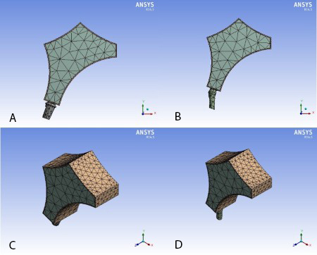
Standard titanium implants (Institut Straumann AG, Basel, Switzerland) with regular necks (4.8×12 mm) were selected for this FEA. A dry skull was used to obtain a digital image of premaxillary bone by photogrammetry system with the aid of a portable Coordinate Measuring Machine (CMM, Rexcan III, VDI/VDE 2634, Germany). The scanned image was transferred as point cloud data to the SolidWorks 3D software (version 2014, Dassault Systemès SolidWorks Corp.) which converted the spatial coordinates into a virtual geometric model. The obtained geometric model was transferred to ANSYS 14.5 Workbench (version 2014, Canonsburg, Pennsylvania, USA) to design and mesh the finite element models according to the free mesh method and by using three-dimensional (3D) solid tetrahedron elements (Figure 1).
Figure 1- Meshed abutment and bone templates. A: Straight abutment, sagittal view. B: Angled abutment, sagittal view. C: Straight abutment, isometric view. D: Angled abutment, isometric view.
Four 3D models were designed by the use of ANSYS 14.5 software: (1) an implant with a straight titanium abutment, (2) an implant with a straight zirconia abutment, (3) an implant with a 20° angled titanium abutment, and (4) an implant with a 20° angled zirconia abutment in the anterior maxilla. The straight abutment model had 5375 elements and 11058 nodes, while the angulated abutment model had 6225 elements and 12386 nodes. The modelled maxilla included the palatine process of maxilla, palatine bone, and residual alveolar process. The modelled anterior maxillary bone had type 3 bone quality according to the classification by Lekholm and Zarb. (2) In the anterior maxilla, thin cortical bone surrounds a core of trabecular bone. The thickness of cortical bone was considered to be 0.5 mm according to a study by Saab et al. (2) All of the connections between the elements were considered as bonded. The mechanical properties (Table 1), boundary conditions, and the nature of loading were obtained from relevant studies. (9-18) The boundary conditions were determined as fixed support. The models were assumed to be homogenous, isotropic, and linear elastic. The Young's modulus and Poisson's ratio values were entered into ANSYS 14.5 software which automatically calculated the bulk modulus and shear modulus.
Table 1. Mechanical properties of the materials
The implant-abutment assembly was inserted into the alveolar bone at a 113° angle relative to the anterior nasal spine-posterior nasal spine (ANS-PNS) line which is considered as the reference line in similar studies. (8-11) The ANS-PNS line was horizontally oriented. Since the assessment of stress distribution at the abutment-prosthesis interface was not part of the study, the crowns over the abutments were omitted.
The contact between the incisal edges of mandibular incisors and the palatal surfaces of maxillary incisors forms a 130° angle. It is assumed that the load applied to the palatal surfaces of maxillary incisors is parallel to the long axes of mandibular incisors. In addition, a buccally and apically directed load applied to the cingulum simulates a clinical situation where mandibular incisors occlude on the lingual surfaces of maxillary incisors in a centric occlusion. (13,14) Consequently, the load was applied to the cingulum at a 130° angle relative to the long axis of the implant placed in the anterior maxilla (Figure 2).
The magnitude of the load was chosen to be 178 N, which was within the range reported by previous studies. (13-15)
A linear static analysis was performed on the prepared 3D models. The results were extracted in the form of stress and strain contours. The maximum von Mises stress and elastic strain in the abutments and the surrounding cortical and cancellous bones were measured. The colours in the figure legends indicate the levels of stress and strain ranging from dark blue (the lowest) to red (the highest).
Results
The values of maximum von Mises stress and elastic strain in the abutments and the surrounding bone are summarized in Table 2 and Figure 3. The results show that higher levels of stress and strain were transferred to the abutments than to the bone. The patterns of stress and strain distribution were similar in cortical and cancellous bones. Moreover, stress and strain mostly concentrated at the coronal one-third of crestal bone, i.e. at the implant-abutment joint in the labial surface, while the values declined from the implant-abutment joint towards the apical part of the implant. Moreover, more stress concentrated in the zirconia abutment in comparison with the titanium abutment, while the stress distribution, elastic strain, and deformation in the bone were slightly lower around the zirconia abutments in comparison with titanium abutments. Nevertheless, the abutment's material had a less considerable effect on the level of stress and strain transferred to the bone compared to the angle of the abutment. Also, stress and strain were higher in the labial surface compared to the palatal surface of the surrounding bone (Figures 4 and 5). Angulated abutments transferred lower levels of stress and strain to the surrounding bone compared to straight abutments (Figures 4 to 6). Since elastic analysis was performed on the models, similar behaviour can be anticipated with regard to elastic strain and deformation. Angled titanium abutments created 28.5% less strain in the surrounding bone than straight titanium abutments, while angled zirconia abutments created 15% less strain than straight zirconia abutments. In general, strain concentration in cortical bone was slightly higher than that in cancellous bone (Table 2, Figure 6).
Table 2. Maximum von Mises stress and elastic strain in the abutments and the surrounding bone
Figure 2- Schematic view of the direction of load application. A: Straight abutment. B: Angled abutment
Figure 3- Comparison of the maximum von Mises stress in the four simulated models. A: In the whole geometry.
B: In cortical bone. C: In cancellous bone. D: In the abutments.
Figure 4- Stress distribution in cortical bone for the simulated models. A: model І. B: model ІІ. C: model ІІІ. D: model ІV.
Figure 5- Stress distribution in cancellous bone for the simulated models. A: model І. B: model ІІ. C: model ІІІ. D: model ІV.
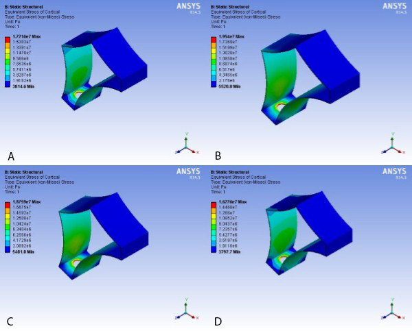
Figure 6- Stress distribution in cancellous bone from isometric view. A: In straight titanium abutment mode. B: In 20° angled titanium abutment mode. C: In straight zirconia abutment mode. D: In 20° angled zirconia abutment mode
Discussion
Low cost, flexibility, high accuracy, and lack of need for refined equipment are some of the advantages of FEA. (12-18) By using this method, it is possible to determine the level and pattern of stress and strain distributions in complex structures. Of course, the design, geometry, mechanical properties, magnitude, and direction of load application can considerably change the results. (12-18)
In the present study, the finite element models were meshed with different number of elements ranging from 5000 to 11000 to confirm the objectivity of the results of von Mises stress, and it was proven that the stress values did not have a correlation with the number of elements in the mentioned range. Moreover, the maximum strain values in the models were within a fixed range.
In general, maxillary and mandibular models consist of a core of cancellous bone and a surrounding layer of cortical bone. Cancellous bone has a Young’s modulus lower than that of cortical bone. Thus, the applied loads distribute in cancellous bone, while the cortical bone absorbs most of the stress. The results of the current FEA showed that the maximum stress and strain concentrated at the coronal one-third of cortical bone, which is similar to the findings of other similar finite element studies. (5,18-24) Several researchers have agreed that the maximum stress concentration is usually detected within the cortical layer, (5-12) which may be attributed to the material properties allocated to the bone model in FEA. (25,26) It has been demonstrated that maxillary and mandibular models comprising of a cancellous core with a Young`s modulus lower than that of cortical bone may simulate a situation where the implants are supported only by the cortical layer. (5,18-24) On the other hand, since the fulcrum is at the coronal one-third, and the response forces in this area oppose the applied load, the maximum stress and strain levels are created in the mentioned region.
In addition, the results indicated that the levels of stress and strain were higher in the labial surface of the peri-implant bone. Considering the fact that the loads were applied from the palatal surface and since the labial bone is less bulky than the palatal bone, stress and strain distribute more intensely in the labial bony surface.
The findings of the present analysis indicated that although the angled positioning of the abutment increases the stress and strain within the abutment, it decreases the stress and strain in the surrounding bone. On the other hand, when zirconia was used instead of titanium, stress was higher in the abutment but slightly lower in the surrounding bone and in the whole geometry. This can be attributed to the higher Young's modulus of zirconia in comparison with titanium.
Papavasiliou et al stated that an angled application of load might lead to overloading the bone around single implants. (4) However, experimental and clinical reports by Saab et al (2), Sethi et al (5), Arun Kumar et al (6), Hasan et al (7), Wu et al (8), Tian et al (9), Kao et al (10), and Canay et al (11) revealed contrary results as they concluded that angled abutments may be a suitable modality when implants cannot be placed in ideal axial positions.
Clelland et al placed abutments with different angulations in the anterior maxillary area and applied masticatory forces along the long axes of the abutments to simulate an edge-to-edge occlusion in the clinical setting. (16) Since masticatory forces significantly decrease in mandibular eccentric positions, their results may be overstated as they concluded that the peak compressive stress for the 20° angled abutments was slightly above the physiological threshold. (16)
According to the principles of biomechanics, several methods have been used in order to decrease the torque in the anterior maxilla such as the use of angulated abutments and providing a horizontal lingual stop on the palatal surface. (25,26) According to Weinberg, if angulated abutments are used, the distance from the resultant line of force to the center of rotation of the implant would decrease, and a lower torque would be applied to the implant (torque=resultant line of force × distance). (27)
In FEA, models are considered isotropic and homogenous to simplify calculation procedures. (15-17) However, bone is an anisotropic material, which means that when it is evaluated at different directions, it shows different mechanical properties. (26-33) Some researchers have attempted to reconstruct maxillary and mandibular models with some degrees of anisotropy. O`Mahony et al evaluated the pattern of stress distribution in two mandibular models: one completely isotropic and the other transversely isotropic, and found that in the latter, the amount of stress in crestal bone was 20% higher than that in the former. (28)
What differentiates the present study from previous works is that the implants were designed with the exact coordinates and based on the data presented by the manufacturing company. In addition, the obtained values were compared with the physiological threshold proposed by Frost. (29) According to Frost, bone remodeling stops when maximum strain-causing loads are below 1500 µstrain. However, the bone remodels when strain values reach 1500-3000 µstrain. Strain values exceeding 4000 µstrain cause pathological bone deformation .(29) In the current study, both straight and angulated abutments created strain levels in the surrounding bone within the physiological threshold and lower than 1000 µstrain.
The stress and strain values obtained in the current study were lower than those reported by Saab et al since they used two-dimensional (2D) FEA. (2) 3D FEA shows stress distribution in three dimensions, and consequently, the obtained values would be lower than those acquired from 2D models and could more realistically simulate the clinical situation. (25,30,31,33)
Conclusions
Within the limitations of the present study, it can be concluded that stress and strain levels generated by both straight and angled abutments are within the physiological threshold. Although the level of stress and strain in angled abutments may be high, these abutments create lower stress and strain levels in the surrounding cortical and cancellous bones compared to straight abutments. The material of the abutment has a less considerable effect on stress and strain distribution compared to the angle of the abutment. Stress and strain levels are higher in zirconia abutments in comparison with titanium abutments.
Full-Text: (775 Views)
Abstract
Background and Aim: Dental implants with angled abutments are often inserted in the anterior maxillary region due to the status of the residual ridge and aesthetic considerations. The purpose of this study was to assess stress and strain distributions in the premaxillary bone around dental implants by means of finite element analysis (FEA).
Materials and Methods: Four three-dimensional (3D) finite element models were designed by using ANSYS 14.5 software: (1) a straight titanium abutment, (2) a straight zirconia abutment, (3) a 20° angled titanium abutment, and (4) a 20° angled zirconia abutment in the anterior maxilla. Standard Straumann® implants with regular necks (4.8×12 mm) were selected. Premaxillary bone with type 3 bone quality was modelled with a 0.5-mm-thick cortical layer. A 178-N oblique load was applied to the cingulum of the models. Afterwards, stress and strain distributions were measured by using ANSYS 14.5 software.
Results: Maximum stress and strain concentrated at the implant-abutment joint at the cervical one-third of crestal bone, mainly in the labial surface. The abutment's material had a less substantial effect on the distribution of stress and strain compared to the angle of the abutment. Stress and strain concentration in angled abutments was higher than that in straight abutments. However, angled abutments transferred lower levels of stress and strain to the bone compared to straight abutments.
Conclusion: It can be concluded that an angled abutment might decrease the stress and strain in the anterior maxillary bone in comparison with straight abutments.
Key words: Abutment, Dental Implant, Finite Element Analysis
Introduction
The principles of biomechanics must be prudently measured in the design of implant-supported fixed partial dentures (FPDs). (1) The functional loads applied to prostheses are transferred through the implants to the surrounding bone. However, the bone can only tolerate physiological strain and stress levels. (2-4)
The implants placed in the anterior maxillary region often have a lower survival rate than those placed in the anterior mandibular area. (1-3) Moreover, the pattern of bone loss cannot be accurately predicted in the anterior maxilla after tooth loss. (2) Due to the changes in the bone morphology of the anterior maxillary area, it has become an increasingly common practice to place the implants in angled positions in order to comply with space limitations and aesthetic needs. (5-7)
In protrusive mandibular excursions, palatal surfaces of maxillary incisors serve as a vertical guide for mandibular incisors. (3) Therefore, occlusal loads are often applied at an angled direction to the long axes of the implants which substitute anterior teeth. Most of the studies that focus on the biomechanics of implants have concluded that stress mainly concentrates at the implant-bone interface at the level of crestal bone.(7-9) Angulation of the abutment is an important variable that needs further assessments. (1)
Finite element analysis (FEA) can predict mechanical behaviour in complex structures by dividing the structure into smaller elements. Since these elements are interconnected with nodes, the whole structure will be affected under pressure. As the implant and its surrounding bone have a very intricate structure, the changes caused by functional forces can be carefully monitored by using FEA. (10-12)
The purpose of this FEA was to assess stress and strain distributions in the peri-implant bone of the anterior maxillary region with two different abutment materials and abutment designs.
Materials and Methods
Standard titanium implants (Institut Straumann AG, Basel, Switzerland) with regular necks (4.8×12 mm) were selected for this FEA. A dry skull was used to obtain a digital image of premaxillary bone by photogrammetry system with the aid of a portable Coordinate Measuring Machine (CMM, Rexcan III, VDI/VDE 2634, Germany). The scanned image was transferred as point cloud data to the SolidWorks 3D software (version 2014, Dassault Systemès SolidWorks Corp.) which converted the spatial coordinates into a virtual geometric model. The obtained geometric model was transferred to ANSYS 14.5 Workbench (version 2014, Canonsburg, Pennsylvania, USA) to design and mesh the finite element models according to the free mesh method and by using three-dimensional (3D) solid tetrahedron elements (Figure 1).
Figure 1- Meshed abutment and bone templates. A: Straight abutment, sagittal view. B: Angled abutment, sagittal view. C: Straight abutment, isometric view. D: Angled abutment, isometric view.
Four 3D models were designed by the use of ANSYS 14.5 software: (1) an implant with a straight titanium abutment, (2) an implant with a straight zirconia abutment, (3) an implant with a 20° angled titanium abutment, and (4) an implant with a 20° angled zirconia abutment in the anterior maxilla. The straight abutment model had 5375 elements and 11058 nodes, while the angulated abutment model had 6225 elements and 12386 nodes. The modelled maxilla included the palatine process of maxilla, palatine bone, and residual alveolar process. The modelled anterior maxillary bone had type 3 bone quality according to the classification by Lekholm and Zarb. (2) In the anterior maxilla, thin cortical bone surrounds a core of trabecular bone. The thickness of cortical bone was considered to be 0.5 mm according to a study by Saab et al. (2) All of the connections between the elements were considered as bonded. The mechanical properties (Table 1), boundary conditions, and the nature of loading were obtained from relevant studies. (9-18) The boundary conditions were determined as fixed support. The models were assumed to be homogenous, isotropic, and linear elastic. The Young's modulus and Poisson's ratio values were entered into ANSYS 14.5 software which automatically calculated the bulk modulus and shear modulus.
Table 1. Mechanical properties of the materials
The implant-abutment assembly was inserted into the alveolar bone at a 113° angle relative to the anterior nasal spine-posterior nasal spine (ANS-PNS) line which is considered as the reference line in similar studies. (8-11) The ANS-PNS line was horizontally oriented. Since the assessment of stress distribution at the abutment-prosthesis interface was not part of the study, the crowns over the abutments were omitted.
The contact between the incisal edges of mandibular incisors and the palatal surfaces of maxillary incisors forms a 130° angle. It is assumed that the load applied to the palatal surfaces of maxillary incisors is parallel to the long axes of mandibular incisors. In addition, a buccally and apically directed load applied to the cingulum simulates a clinical situation where mandibular incisors occlude on the lingual surfaces of maxillary incisors in a centric occlusion. (13,14) Consequently, the load was applied to the cingulum at a 130° angle relative to the long axis of the implant placed in the anterior maxilla (Figure 2).
The magnitude of the load was chosen to be 178 N, which was within the range reported by previous studies. (13-15)
A linear static analysis was performed on the prepared 3D models. The results were extracted in the form of stress and strain contours. The maximum von Mises stress and elastic strain in the abutments and the surrounding cortical and cancellous bones were measured. The colours in the figure legends indicate the levels of stress and strain ranging from dark blue (the lowest) to red (the highest).
Results
The values of maximum von Mises stress and elastic strain in the abutments and the surrounding bone are summarized in Table 2 and Figure 3. The results show that higher levels of stress and strain were transferred to the abutments than to the bone. The patterns of stress and strain distribution were similar in cortical and cancellous bones. Moreover, stress and strain mostly concentrated at the coronal one-third of crestal bone, i.e. at the implant-abutment joint in the labial surface, while the values declined from the implant-abutment joint towards the apical part of the implant. Moreover, more stress concentrated in the zirconia abutment in comparison with the titanium abutment, while the stress distribution, elastic strain, and deformation in the bone were slightly lower around the zirconia abutments in comparison with titanium abutments. Nevertheless, the abutment's material had a less considerable effect on the level of stress and strain transferred to the bone compared to the angle of the abutment. Also, stress and strain were higher in the labial surface compared to the palatal surface of the surrounding bone (Figures 4 and 5). Angulated abutments transferred lower levels of stress and strain to the surrounding bone compared to straight abutments (Figures 4 to 6). Since elastic analysis was performed on the models, similar behaviour can be anticipated with regard to elastic strain and deformation. Angled titanium abutments created 28.5% less strain in the surrounding bone than straight titanium abutments, while angled zirconia abutments created 15% less strain than straight zirconia abutments. In general, strain concentration in cortical bone was slightly higher than that in cancellous bone (Table 2, Figure 6).
Table 2. Maximum von Mises stress and elastic strain in the abutments and the surrounding bone
Figure 2- Schematic view of the direction of load application. A: Straight abutment. B: Angled abutment
Figure 3- Comparison of the maximum von Mises stress in the four simulated models. A: In the whole geometry.
B: In cortical bone. C: In cancellous bone. D: In the abutments.
Figure 4- Stress distribution in cortical bone for the simulated models. A: model І. B: model ІІ. C: model ІІІ. D: model ІV.
Figure 5- Stress distribution in cancellous bone for the simulated models. A: model І. B: model ІІ. C: model ІІІ. D: model ІV.
Figure 6- Stress distribution in cancellous bone from isometric view. A: In straight titanium abutment mode. B: In 20° angled titanium abutment mode. C: In straight zirconia abutment mode. D: In 20° angled zirconia abutment mode
.jpg)
Discussion
Low cost, flexibility, high accuracy, and lack of need for refined equipment are some of the advantages of FEA. (12-18) By using this method, it is possible to determine the level and pattern of stress and strain distributions in complex structures. Of course, the design, geometry, mechanical properties, magnitude, and direction of load application can considerably change the results. (12-18)
In the present study, the finite element models were meshed with different number of elements ranging from 5000 to 11000 to confirm the objectivity of the results of von Mises stress, and it was proven that the stress values did not have a correlation with the number of elements in the mentioned range. Moreover, the maximum strain values in the models were within a fixed range.
In general, maxillary and mandibular models consist of a core of cancellous bone and a surrounding layer of cortical bone. Cancellous bone has a Young’s modulus lower than that of cortical bone. Thus, the applied loads distribute in cancellous bone, while the cortical bone absorbs most of the stress. The results of the current FEA showed that the maximum stress and strain concentrated at the coronal one-third of cortical bone, which is similar to the findings of other similar finite element studies. (5,18-24) Several researchers have agreed that the maximum stress concentration is usually detected within the cortical layer, (5-12) which may be attributed to the material properties allocated to the bone model in FEA. (25,26) It has been demonstrated that maxillary and mandibular models comprising of a cancellous core with a Young`s modulus lower than that of cortical bone may simulate a situation where the implants are supported only by the cortical layer. (5,18-24) On the other hand, since the fulcrum is at the coronal one-third, and the response forces in this area oppose the applied load, the maximum stress and strain levels are created in the mentioned region.
In addition, the results indicated that the levels of stress and strain were higher in the labial surface of the peri-implant bone. Considering the fact that the loads were applied from the palatal surface and since the labial bone is less bulky than the palatal bone, stress and strain distribute more intensely in the labial bony surface.
The findings of the present analysis indicated that although the angled positioning of the abutment increases the stress and strain within the abutment, it decreases the stress and strain in the surrounding bone. On the other hand, when zirconia was used instead of titanium, stress was higher in the abutment but slightly lower in the surrounding bone and in the whole geometry. This can be attributed to the higher Young's modulus of zirconia in comparison with titanium.
Papavasiliou et al stated that an angled application of load might lead to overloading the bone around single implants. (4) However, experimental and clinical reports by Saab et al (2), Sethi et al (5), Arun Kumar et al (6), Hasan et al (7), Wu et al (8), Tian et al (9), Kao et al (10), and Canay et al (11) revealed contrary results as they concluded that angled abutments may be a suitable modality when implants cannot be placed in ideal axial positions.
Clelland et al placed abutments with different angulations in the anterior maxillary area and applied masticatory forces along the long axes of the abutments to simulate an edge-to-edge occlusion in the clinical setting. (16) Since masticatory forces significantly decrease in mandibular eccentric positions, their results may be overstated as they concluded that the peak compressive stress for the 20° angled abutments was slightly above the physiological threshold. (16)
According to the principles of biomechanics, several methods have been used in order to decrease the torque in the anterior maxilla such as the use of angulated abutments and providing a horizontal lingual stop on the palatal surface. (25,26) According to Weinberg, if angulated abutments are used, the distance from the resultant line of force to the center of rotation of the implant would decrease, and a lower torque would be applied to the implant (torque=resultant line of force × distance). (27)
In FEA, models are considered isotropic and homogenous to simplify calculation procedures. (15-17) However, bone is an anisotropic material, which means that when it is evaluated at different directions, it shows different mechanical properties. (26-33) Some researchers have attempted to reconstruct maxillary and mandibular models with some degrees of anisotropy. O`Mahony et al evaluated the pattern of stress distribution in two mandibular models: one completely isotropic and the other transversely isotropic, and found that in the latter, the amount of stress in crestal bone was 20% higher than that in the former. (28)
What differentiates the present study from previous works is that the implants were designed with the exact coordinates and based on the data presented by the manufacturing company. In addition, the obtained values were compared with the physiological threshold proposed by Frost. (29) According to Frost, bone remodeling stops when maximum strain-causing loads are below 1500 µstrain. However, the bone remodels when strain values reach 1500-3000 µstrain. Strain values exceeding 4000 µstrain cause pathological bone deformation .(29) In the current study, both straight and angulated abutments created strain levels in the surrounding bone within the physiological threshold and lower than 1000 µstrain.
The stress and strain values obtained in the current study were lower than those reported by Saab et al since they used two-dimensional (2D) FEA. (2) 3D FEA shows stress distribution in three dimensions, and consequently, the obtained values would be lower than those acquired from 2D models and could more realistically simulate the clinical situation. (25,30,31,33)
Conclusions
Within the limitations of the present study, it can be concluded that stress and strain levels generated by both straight and angled abutments are within the physiological threshold. Although the level of stress and strain in angled abutments may be high, these abutments create lower stress and strain levels in the surrounding cortical and cancellous bones compared to straight abutments. The material of the abutment has a less considerable effect on stress and strain distribution compared to the angle of the abutment. Stress and strain levels are higher in zirconia abutments in comparison with titanium abutments.
Type of Study: Original article |
Subject:
Dental implant
References
1. Cavallaro J Jr, Greenstein G. Angled implant abutments: a practical application of available knowledge. J Am Dent Assoc. 2011 Feb;142(2):150-8.
2. Saab XE, Griggs JA, Powers JM, Engelmeier RL. Effect of abutment angulation on the strain on the bone around an implant in the anterior maxilla: A finite element study. J Prosthet Dent. 2007 Feb;97(2):85-92.
3. Levin BP, Rubinstein S, Rose LF. Advanced aesthetics management of dental implants: surgical and restorative considerations to improve outcomes. J Esthet Restor Dent. 2015 Jul-Aug;27(4):224-30.
4. Papavasiliou G, Kamposiora P, Bayne SC, Fellton DA. Three dimensional finite element analysis of stress-distribution around single tooth implants as a function of bony support, prosthesis type, and loading during function. J Prosthet Dent. 1996 Dec;76(6):633-40.
5. Sethi A, Kaus T, Sochor P. The use of angulated abutments in implant dentistry: five-year clinical results of an ongoing prospective study. Int J Oral Maxillofac Implants. 2000 Nov-Dec;15(6):801-10.
6. Arun Kumar G, Mahesh B, George D. Three dimensional finite element analysis of stress distribution around implant with straight and angled abutments in different bone qualities. J Indian Prosthodont Soc. 2013 Dec;13(4):466–72.
7. Hasan I, Roger B, Heinemann F, Keilig L, Bourauel C. Influence of abutment design on the success of immediately loaded dental implants: experimental and numerical studies. Med Eng Phys. 2012 Sep;34(7):817-25.
8. Wu T, Liao W, Dai N, Tang C. Design of a custom angled abutment for dental implants using computer-aided design and nonlinear finite element analysis. J Biomech. 2010 Jul 20;43(10):1941-6.
9. Tian K, Chen J, Han L, Yang J, Huang W, Wu D. Angled abutments result in increased or decreased stress on surrounding bone of single-unit dental implants: a finite element analysis. Med Eng Phys. 2012 Dec;34(10):1526-31.
10. Kao HC, Gung YW, Chung TF, Hsu ML.The influence of abutment angulation on micromotion level for immediately loaded dental implants: A 3-D Finite element Analysis. Int J Oral Maxillofac Implants. 2008 Jul-Aug;23(4):623-30.
11. Canay S, Hersek N, Akpinar I, Asik Z. Comparison of stress distribution around vertical and angled implants with finite-element analysis. Quintessence Int. 1996 Sep;27(9):591-8.
12. Geramy A, Morgano SM. Finite element analysis of three designs of an implant-supported molar crown. J Prosthet Dent. 2004 Nov;92(5):434-40.
13. Hellsing G. On the regulation of interincisor bite force in man. J Oral Rehabil. 1980 Sep;7(5):403-11.
14. Helkimo E, Carlsson GE, Helkimo M. Bite force and state of dentition. Acta Odontol Scand. 1977;35(6):297-303.
15. Geng JP, Tan KB, Liu GR. Application of finite element analysis in implant dentistry: a review of the literature. J Prosthet Dent. 2001 Jun;85(6):585-98.
16. Clelland NL, Lee JK, Bimbenet OC, Brantley WA. A three- dimensional finite element stress analysis of angled abutments for an implant placed in the anterior maxilla. J Prosthodont. 1995 Jun;4(2):95-100.
17. Hasan I, Bourauel C, Keilig L, Reimann S, Heinemann F. The influence of implant number and abutment design on the biomechanical behaviour of bone for an implant-supported fixed prosthesis: a finite element study in the upper anterior region.Comput Methods Biomech Biomed Engin. 2011 Dec;14(12):1113-6.
18. Jafari k, Vojdani M, Mahdavi F, Heidary H. Finite element analysis of the effect of superstructure materials and loading angle on stress distribution around the implant. J Dent Biomater. 2014;1(2):57-62.
19. Sadrimanesh R, Siadat H, Sadr-Eshkevari P, Monzavi A, Maurer P, Rashad A. Alveolar bone stress around implants with different abutment angulation: an FE-analysis of anterior maxilla. Implant Dent. 2012 Jun;21(3):196-201.
20. Bahuguna R, Anand B, Kumar D, Aeran H, Anand V, Gulati M. Evaluation of stress patterns in bone around dental implant for different abutment angulations under axial and oblique loading. A finite element analysis. Natl J Maxillofac Surg. 2013 Jan;4(1):46-51.
21. Wu D, Tian K, Chen J, Jin H, Huang W, Liu Y.A further finite element stress analysis of angled abutments for an implant placed in the anterior maxilla. Comput Math Methods Med.2015;2015:560645.
22. Danza M, Palmieri A, Farinella F, Brunelli G, Carinci F, Girardi A, et al. Three dimensional finite element analysis to detect stress distribution in spiral implants and surrounding bone. Dent Res J (Isfahan). 2009 Fall;6(2):59-64.
23. Cardelli P, Montani M, Gallio M, Biancolini M, Brutti C, Barlattani A. Angulated abutments and periimplants stress: F.E.M. Analysis. Oral Implantol (Rome). 2009 Jan;2(1):3-10.
24. Geng JP, Xu DW, Tan KB, Liu GR. Finite element analysis of an osseointegrated stepped screw dental implan. J Oral Implantol. 2004;30(4):223-33.
25. Las Casas EB, Ferreira PC, Cimini CA Jr, Toledo EM, Barra LP, Cruz M. Comparative 3D finite element stress analysis of straight and angled wedge-shaped implant designs. Int J Oral Maxillofac Implants. 2008 Mar-Apr;23(2):215-25.
26. Holmes DC, Loftus JT. Influence of bone quality on stress distribution for endosseous implants. J Oral Implantol. 1997;23(3):104-11.
27. Weinberg LA. Reduction of implant loading with therapeutic biomechanics. Implant Dent. 1998;7(4):277-85.
28. O`Mahony A, Williams JL, Spencer P. Anisotropic elasticity of cortical and cancellous bone in the posterior mandible increase peri-implant stress and strain under oblique loading. Clin Oral Implants Res. 2001 Dec;12(6):648-57.
29. Frost HM. Bone "mass" and the "mechanostat": a proposal. Anat Rec. 1987 Sep;219(1):1-9.
30. Ismail YH, Pahountis LN, Fleming JF. Comparison of two-dimensional and three dimensional finite element analysis of a blade implan. Int J Oral Implantol.1987;4(2):25-31.
31. Ebadian B, Mosharraf R, Abbasi S, Memar Ardestani P, Farzin M.The effect of implant angulation and splinting on stress distribution in implant body and supporting bone: A finite element analysis.Eur J Dent. 2015 Jul-Sep;9(3):311–8.
32. Solberg k, Heinemann F, Pellikaan P, Keilig L, Stark H, Bourauel C,et al. Finite element analysis of different loading conditions for implant-supported overdentures supported by conventional or mini implants.Computer Methods Biomech Engin 2017 May;20(7):770-82.
33. Moon SY, Lim YJ, Kim MJ, Kwon HB. Three-dimensional finite element analysis of platform switched implant. J Adv Prosthodont. 2017 Feb;9(1):31–7.
| Rights and permissions | |
 |
This work is licensed under a Creative Commons Attribution-NonCommercial 4.0 International License. |
